This is an old revision of the document!
Steppermotor controlled by Arduino
This is a short how-to on controlling a bipolar stepper motor by an Arduino and a L298N based dual H-bridge controller board.
For a long time I thought about playing around with a stepper motor. The goal for this page is not to explain what a stepper motor is, but to document for myself What I did so I can reproduce the results at a later time.
The Wiki page on stepper motors does an excellent job at documenting the motor.
The components
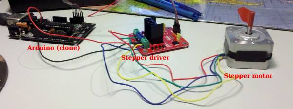
This first test setup has three components, an Arduino (clone), A stepper driver and a stepper motor.
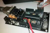
The Arduino clone is just like a regular Arduino but this one has a serial port and the labeling of the ports is more like the real Atmega328 pin mapping.
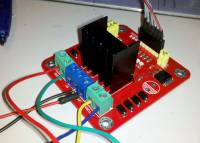
 The controller board was a bit of a chalange because I tried to design it myself with the two chips that were designed specifically for this: the L297 STEPPER MOTOR CONTROLLERSL297 STEPPER MOTOR CONTROLLERS and the [[http://www.st.com/internet/com/TECHNICAL_RESOURCES/TECHNICAL_LITERATURE/DATASHEET/CD00000240.pdf|L298 Dual Full Bridge Driver]. This is no simple task if you need to do it on a single layer PCB. So in the end I just bought the simpler L298 driver board so I could get started.

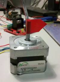
The steppermotor I chose also came from e-bay, it works on 12V and it is unipolar. In the end the problem with this motor is that the wire coloring is different from any data-sheet I could find. So after a lot of searching and testing I came up with the right sequence.
 Coil A : Blue
Coil B : Yellow
Coil C : Green
Coil D : Red
