This is an old revision of the document!
Spectrumanaliser Hardware
There are four hardware components in my spectrumanaliser project;
- Power-supply
- Opamp
- Arduino (clone)
- Display
Here is a short description of why they are needed and how they are connected.

Power-supply
Usually I would not mention this separately but there is one important thing to know about powering this project.
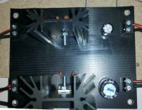 The Opamp (audio amplifier) is very sensitive. If there is a lot of noise on the power supply then the opamp will pick up this interference. So the best thing to do, to prevent interference from the display on the audio signal, is to have one power source for the Arduino + opamp, and another one for only the display.
The Ground (0 Volt line) of both supplies must be connected (of course) so the 5V level of both supplies are the same 5V above ground. If you do not connect the ground together, you will get two “floating” 5V lines. Both are 5V but what level is the one 5V relative to the other 5V? This is why you must join the ground lines to each other.
I simply made two 7805 circuits and joined the ground together.
Opamp
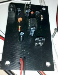
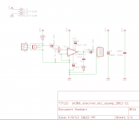 The opamp is based on a LM386. This is a very standard opamp that (also) works on 5 Volt. There is one thing to consider, the ADC (Analog to Digital Converter) on the Arduino can read 0V to 5V, but no negative values. So the output on pin1 of JP4 (see schematic) is 2.5V in silence, and sound can produce up to 0V to 5V. And this is exactly what is useful for the Arduino. On regular audio projects you would like the AC (-2.5V to 2.5V) signal; this comes out of pin2 of JP4 (see schematic).
The input for this opamp can be a ecectret condensor microphone, but if you adjust the pot, you can also use a line-in signal from a music-player.
Arduino (clone)
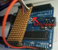
 This should speak for its self, I used a Atmega328P based Arduino (a.k.a. Arduino UNO). And the clone I have works just as well.
The library for driving the LED display actually addresses a “port” on the Arduino, so you need to find out where “portb” is. In some other page I will describe the software and the libraries I used, you will see the “portb” there again.
Actually, the clone board has the “portb” marked much clearer so finding the right pins was much easier.
Display
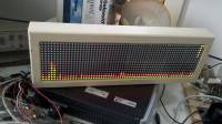
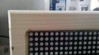 For the LED display, I used two of the Sure Electronics DE-DP14211 bi-colour (red-green) 16*32 5mm LED displays. Giving me a total of 16*64 LEDs. This is very practical as there are 2^6 (two to the power of 6) = 64 channels that I calculate using the (fast) Fourier transformations.
This display shares the ground (0 Volt line) with the Arduino, but it is on its own 5V power supply. This is because, ones the display it operating, there is some distortion on the power supply. This will interfere with the opamp. So just give the display its own power supply and there are no worries about that.