Table of Contents
I2C pcf8574 8bit port expander
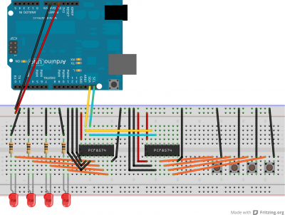
I made a test / prototype setup on a breadboard with two pcf8574 ics ; one for output and one for input. Both connected to the same I2C bus.
Adding more digital inputs to an Arduino was my first objective, as I am planning to use this on a project which has buttons that control a menu.
For now this little write-up should suffice for the moment I am going to design a PCB for this.
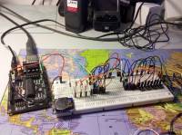
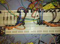
The breadboard built
The four resistors are 100Ω
The four LEDs are regular red 3mm leds
The four buttons are momentary on push buttons
Fritzing
 The program called Fritzing does a nice job of making an understandable picture of the board.
This is not only nice for using in a write-up but in real-live it is faster than pulling everything from your breadboard just to place components a couple of holes further away (because you need the extra space).
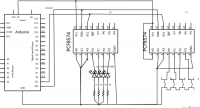
Fritzing can also make a schematic, I've included it here but it looks horrible. When I make the final design on a PCB I will use Eagle for this.

Breadboard
The code
The Arduino IDE has a library called Wire which is used for I2C stuff.
I wrote code that reads the button input and writes this to the LED output:
- PCF8574.ino
// I2C PCF8574 8 bit i/o port expander
// by AEP
//
// testing / prototyping the Wire library in combination with the ic PCF8574
// Reads data from PCF8574 over I2C and sends data to another PCF8574 over the same I2C bus


// Created 21 oct 2012

#include <Wire.h>

byte iInput=0;
byte iOutput=0;

void setup()
{
  Wire.begin();
}

void loop()
{
  Wire.requestFrom(33,1);// Begin transmission to PCF8574 with the buttons
  if(Wire.available())   // If bytes are available to be recieved
  {
    iInput = Wire.read();// Read a byte
  }

  if(iInput<255)         //If the value less than 255
  {
    if (iInput==254) // P0
    {
      iOutput = 1;
    };
    if (iInput==253) // P1
    {
      iOutput = 2;
    };
    if (iInput==251) // P2
    {
      iOutput = 4;
    };
    if (iInput==247) // P3
    {
      iOutput = 8;
    };
  }
  Wire.beginTransmission(32);  //Begin transmission to PCF8574 (with the LEDs)
  Wire.write(iOutput);         //Send data to PCF8574 (with the LEDs)
  Wire.endTransmission();      //End Transmission to PCF8574 (with the LEDs)
}

